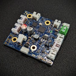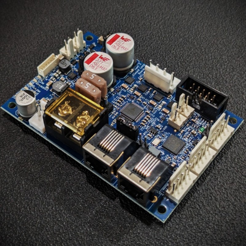


The Duet 3 Expansion 1HCL is a CAN-FD connected expansion board that is designed to provide a high current stepper motor driver, combined with multiple interfaces for position feedback.
Learn More at Duet's Hardware Overview here
The Duet 3 Expansion 1HCL board provides a high current Stepper motor driver, combined with multiple interfaces for position feedback and firmware to implement closed loop position control. In addition it has a number of peripheral inputs and outputs for functions such as sensing motor temperature, controlling a brake and axis endstop. It connects to the Duet 3 CAN-FD bus using RJ11 connectors (same as the Duet 3 Mainboard 6HC, Duet 3 expansion boards, and the tool distribution board). Multiple Duet 3 Expansion 1HCL boards can be daisy chained on the bus, with power (up to 48V) provided locally. This allows for very large machines to be constructed without a significant wiring burden and signal integrity issues.
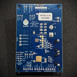
Duet 3 1HCL ToolHead Board
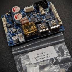
Connector Kit (Including Crimp Sockets)
ARM Cortex-M4F microcontroller running at 120MHz
TMC2160A stepper driver: SPI controlled, can be run in open loop or closed loop mode. Maximum motor current 6.3A peak per phase (4.45A RMS)
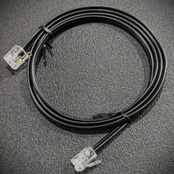
RJ11 CAN In and CAN Out connectors to connect to the Duet 3 CAN-FD bus
Two medium-current (2.5A max recommended) outputs at VIN or VBRAKE voltage with PWM capability and built-in flyback diodes: out0, out1. Optionally provide VBRAKE at a different voltage from VIN to allow (for example) to run the stepper motor at 48V and the brake at 24V. Note the flyback diodes are connected to the voltage being used (VBRAKE or VIN as selected)
Two 3.3V-level PWM capable output (3mA max), through 470R series resistor: io0.out, io1.out, Two digital inputs with permanent 27K pullup resistors, protected against over-voltage: io0.in, io1.in
One thermistor/PT1000 input: temp0. This is intended to allow for motor temperature monitoring (potentially couple with a cooling system controlled by one of the outputs)

You might also like
The Duet 3 Expansion 1HCL is a CAN-FD connected expansion board that is designed to provide a high current stepper motor driver, combined with multiple interfaces for position feedback.